Battery-Buffered DC EV Charging System for Commercial Projects
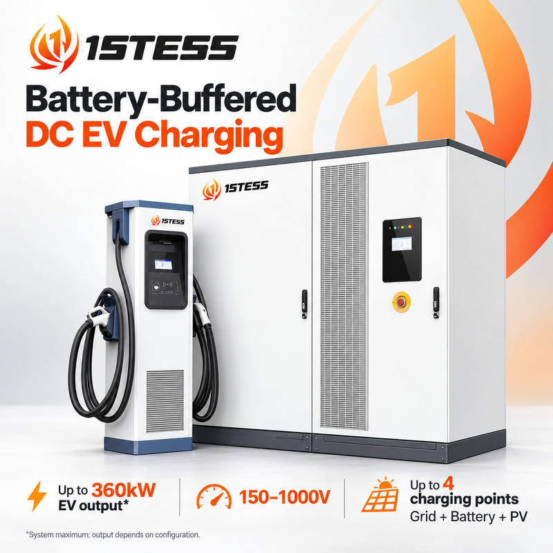
The 1stess battery-buffered DC EV charging system combines grid access, LFP battery storage access and solar PV input in a configurable platform for commercial EV charging projects. Designed for importers, EPC contractors, charging operators and project procurement teams, it supports load shifting and coordinated energy use under a unified EMS strategy. Its specified electrical isolation separates grid, battery, EV and renewable-energy interfaces; final protection design is reviewed for the selected configuration.
The IHS540K2 Power Cube supports up to 360kW total EV charging output across a maximum of four charging points with two dual-connector dispensers. Its 150–1000V DC charging range supports project evaluation for different vehicle voltage requirements. Power is allocated within the configured system; 360kW is not a per-connector rating.
Energy storage access supports up to two LFP battery groups, specified at 200kWh per group. The source specification lists up to 120kW charging from the AC grid to storage and up to 240kW battery-to-EV output with the specified module configurations. PV access supports up to two 30kW MPPT channels. These are separate path limits and must not be added together as a promised simultaneous output.
Choose EXP200-FDC, EXP300-FDC or EXP500-LDC dispensers according to current, connector and site requirements. Dispenser features include a capacitive touchscreen, RFID, emergency stop, DC metering and OCPP 1.6J, with LAN and LTE modem support. Higher-current connections, bidirectional grid feedback, V2G and AC-bus backup require the corresponding options and engineering confirmation.
Send your available grid capacity, vehicle charging requirements, battery capacity, PV capacity and target-market connector standard. 1stess can help define the configuration for fleet depots, commercial parking and charging-hub projects.
Battery-Buffered Charging for Site-Level Energy Planning
Coordinate battery charging and EV demand through the system configuration and EMS strategy. Evaluate load shifting against your site's tariff, grid capacity and operating profile. Actual savings and charging availability depend on the selected system and usage.
Electrical Isolation Across Energy Interfaces
The supplied feature list specifies electrical isolation between grid, battery, EV and renewable-energy inputs. Include the isolation and protection design in the project engineering review; the source does not establish target-market certification or an independently verified safety result.
Separate Power Paths, Clear Engineering Limits
Specify grid-to-storage, grid-to-EV and battery-to-EV requirements separately. This helps engineering teams assess module allocation and charging demand before procurement.
Two Battery Groups and Dual MPPT PV Access
The platform supports a maximum of two battery groups at 200kWh each and up to two 30kW PV MPPT inputs. Battery capacity is an access specification, not a claim that 400kWh is installed inside the pictured Power Cube.
Dispenser Options for Different Project Requirements
Compare the EXP200-FDC, EXP300-FDC and EXP500-LDC current options, cabinet depth, connector selection and project operating needs. System output and selected connector ratings determine the final charging capability.
Controls for Operators and Service Teams
The Power Cube has a 7-inch TFT touchscreen, five LED indicators and emergency stop. Dispensers feature a capacitive touchscreen behind tempered protective glass, two RGB panel LEDs, RFID, DC energy metering and emergency stop.
Verified Specifications from the Supplied Material
| Category |
Supplied specification |
Publication note |
| Platform designation |
IHS540K2 540kW POWER CUBE |
Platform designation; do not advertise 540kW EV output |
| System type |
On-grid, air cooling, LFP battery access |
Backup and grid feedback are separately configured |
| AC supply |
380/480Vac ±10%; 3 phases + N + PE; 45–65Hz |
Confirm target-market wiring and supply |
| Maximum AC input power |
360kW |
Separate from total EV output and other power paths |
| Grid-to-storage charging |
Up to 120kW; 2 × 60kW with 4 ACDC modules |
Source module configuration applies |
| Grid-to-EV distribution |
Up to 240kW |
Source AC distribution limit |
| Battery group access |
Maximum 2 groups |
External battery configuration must be confirmed |
| Battery capacity per group |
200kWh / 280Ah |
Source-stated nominal specification |
| Battery voltage range |
627–806V |
Battery-side range, not EV output range |
| Battery charge/discharge rate |
0.5C; maximum 0.75C discharge for 30 minutes |
Source-stated limits; do not claim continuous 0.75C |
| Battery-to-EV channels |
Maximum 4 |
Depends on module allocation |
| Battery-to-EV power |
Up to 240kW; 4 × 60kW with 8 DCDC modules |
Subject to source module configuration |
| EV charging points |
Maximum 4 with 2 dispensers |
Each dispenser has two connectors |
| Maximum EV charging power |
360kW total |
Shared system maximum, not 360kW per connector |
| EV charging voltage |
150–1000V DC |
Do not confuse with battery voltage |
| PV access |
Maximum 2 channels; 2 × 30kW MPPT |
Final availability depends on configuration |
| AC metering |
One AC energy meter |
Grid side |
| Power Cube HMI |
7-inch TFT touchscreen; 5 LEDs; E-stop |
Preserve actual front-panel layout |
| Power Cube dimensions |
W1000 × H2200 × D1150mm |
Dimensions exclude installation/service clearances |
| Power Cube weight |
928kg with full power modules |
Not a battery-inclusive shipping weight |
| B2G / V2G |
Optional; bidirectional converter configuration required |
Do not present as standard |
| AC-bus backup |
Optional; bidirectional AC2DC configuration required |
No unverified seamless-transfer promise |
Charging Dispenser Comparison
| Specification |
EXP200-FDC |
EXP300-FDC |
EXP500-LDC |
| Output connections |
DC-1 and DC-2 |
DC-1 and DC-2 |
DC-1 and DC-2 |
| DC output voltage |
150–1000V |
150–1000V |
150–1000V |
| Maximum DC output current options |
200A + 200A |
300A + 300A |
200A + 500A or 300A + 500A |
| Dimensions, W × H × D |
500 × 1750 × 260mm |
500 × 1750 × 260mm |
500 × 1750 × 350mm |
| Listed weight |
155kg |
165kg |
190kg |
Dispenser current values are configuration limits. They do not establish simultaneous full-current operation or override the Power Cube's shared power limit.
Common dispenser features in the source: touchscreen LCD, tempered protective glass, two RGB panel LEDs, E-stop, RFID, two DC energy meters, OCPP 1.6J, firmware upgrade support to OCPP 2.0, smart charging/power management, LAN and LTE modem support. OCPP 2.0 upgrade support is not OCPP 2.0 certification.
Source connector options: GB/T 250A with optional 500A; CCS1/CCS2 200A with optional 250A, 300A or 500A; CHAdeMO 125A. Confirm connector/current combinations and target-market requirements before quoting. VDE/PTB metering is listed as an optional certification type; no completed certification is established by the supplied material.
The dispenser source mentions ring-network transfer across three dispensers, whereas the Power Cube table specifies two dispensers/four points. Treat the two-dispenser/four-point configuration as the published system limit until the manufacturer confirms any expanded topology. Do not infer six simultaneously supported charging points.
Frequently Asked Questions
Is the EV charging output 540kW or 360kW?
The source names the platform IHS540K2 540kW Power Cube, while the EV charging specification lists a maximum of 360kW. The 360kW rating is a shared system maximum, subject to configuration.
How many vehicles can the system connect?
The Power Cube specification supports up to four charging points using two dual-connector dispensers. Output is allocated within the configured system limits and vehicle requirements.
Is a 400kWh battery installed inside the Power Cube?
The source specifies access for up to two 200kWh battery groups. It does not establish that 400kWh is built into the pictured cabinet. Battery scope and physical layout must be confirmed for each project.
Can the system integrate solar PV?
The specified PV interface supports up to two 30kW MPPT channels. PV design and actual energy contribution depend on the selected configuration and site conditions.
Are V2G, battery-to-grid and backup operation standard?
No. The source lists these as optional functions dependent on the corresponding bidirectional converter configuration. Confirm the required function, grid rules and control strategy during engineering.
What information is needed for a quotation?
Provide your project country, available grid capacity and voltage, required total charging power, number and type of vehicles, connector standard, target battery capacity, PV capacity, site layout and required communication or billing interfaces.
Configure your battery-buffered DC EV charging system.
Share your project country, available grid capacity and voltage, required total charging power, vehicle count and type, connector standard, target battery capacity, PV capacity, site layout and required communication or billing interfaces. 1stess can help define the configuration for fleet depots, commercial parking and charging-hub projects.


 Your message must be between 20-3,000 characters!